The pressure flush valves made of polyamide from the fittings factory in Leipzig have proven to be a solid construction, the since about 15 been installed as standard in industrial housing construction for years, and their technical structure is so manageable, that it is easily possible for the knowledgeable tenant, to rectify any malfunctions themselves. However, this requires knowledge, how the faucet works.
The sectional model in the picture 1 shows the idle position of the flusher. The piston seal is pressed firmly onto its seat by the water pressure.
picture 2 shows the situation when the flushing lever is pressed. The water now flows unhindered through the flush pipe to the pool. So that when the lever is released, the spiral spring in the upper flushing cap does not immediately push the piston back into place, which would immediately end the rinsing process, is activated by a sensible construction of the closing process 5 to 7 seconds extended, namely, this delay is provided by a bore in the piston with an outlet opening of approx 0,3 mm. The piston can therefore only return to the rest position with the speed, as permitted by the amount of water flowing through the fine channel into the upper part of the flusher.
As a further development of the flush shown in the sectional model, the manufacturer has now placed the compression spring in the lower part of the flush instead of in the cap space. As a result, their service life is indeed increased, because it no longer comes into contact with water; however, is disadvantageous, that it is hardly possible for the layman if a spring breaks, make the replacement yourself, because the connecting pipe to the pool must be dismantled.
The rinsing process takes too long
■ Pipe wrench, screwdriver, Stahldraht, 0,3mm diameter
■ Rubber sealing washer 36 Glutos 30 Glutos 1,5 mm
The overflow channel with 0,3 mm nozzle opening clogs over time, so that the rinsing process is only ended after a very long time (usually by forcibly pushing up the operating lever). To remedy this defect only the clogged nozzle opening needs to be pierced. After closing the valve upstream of the flusher, the flusher cap is unscrewed by hand. When using a pipe wrench (picture 3) extreme caution is required, so that the cap does not break. Also the next step, unscrewing the relief cone (picture 4), requires finesse, so as not to damage the plastic parts. In the case of the further developed flusher, the screwing elements are made of brass.
The nozzle opening of the overflow channel is located directly under the piston ridge. When piercing (picture 5) the opening must not be enlarged. To do this, use either the bristles of a wire brush or the appropriate diameter from the set of nozzle needles, which EBM-Industrievertrieb offers for sale in its specialist shops. Check when assembling, whether the sealing disk on the flushing cap is still in order or whether it needs to be replaced.
Dishwasher runs constantly
In this case, the cause is the damaged piston seal (picture 1,3) to search. After opening the washer – Like previously described – and removing the piston, unscrew its seal with a screwdriver, where to check, whether it just needs to be turned around or whether it needs to be replaced.
dishwasher hits
Hitting the flusher is either on a dried up leather cuff (picture 1,6) or due to an already too large nozzle opening of the overflow channel. In the latter case, the entire piston must be replaced (Order no. 3622-02), a wrinkled leather cuff can usually be made supple again with a commercially available leather grease. Before reinserting the piston, expand the boot slightly with your thumb nail.
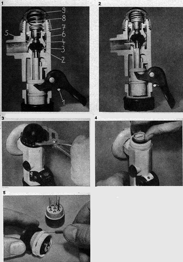 1 Sectional model of the pressure spooler R ¾″ in the closed position. 1 Regulating screw on the operating lever, 2 Seat of the piston seal, 3 Rubber piston seal, 4 Pistons, 5 overflow channel, 6 Ledermanschette, 7 relief cone, 8 compression spring, 9 screw cap
2 Sectional model of the flush valve in working position
3 Be careful when unscrewing the flush cap with the pipe wrench!
4 Unscrew the relief cone
5 Piercing the nozzle opening of the overflow channel